Member-only story
Connecting the Duinotech 3-Axis Compass to an Arduino
The Duinotech 3-Axis Compass Magnetometer Module (Part Number: XC-4496 — see Figure 1) can be purchased from Jaycar Electronics.

Unfortunately, the module comes with no instructions and very brief specifications:
- Operating Voltage: 5VDC (or 3.3 VDC)
- Resolution: 12 bits
- Interface: I2C
- Includes: 5V to 3.3V level shifter (so you can operate it from 5 VDC)
- Dimensions: 20(L) x 16(W) x 5(H) mm
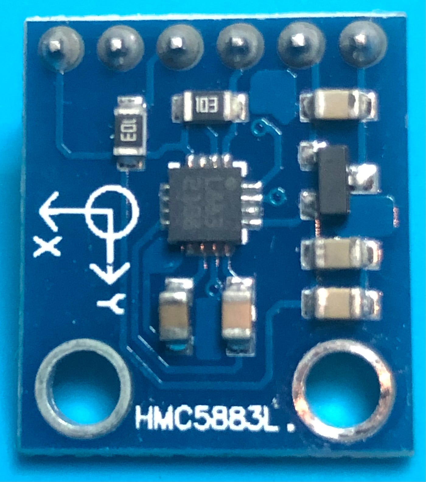
I first wrote about this module in 2015, back when blogger was still a thing. Based on the HMC5883L printed on the PCB (Figure 2), it didn’t take Einstein to work out that this breakout board was based on the 3-Axis Digital Compass IC produced by Honeywell.
The HMC5883L Data Sheet is very comprehensive and explains everything that you need to interface the chip to an Arduino via I2C. The Duinotech module is similar to the one produced by SparkFun. It is in fact an improvement on the SparkFun version in that it can be driven from 5VDC and the interrupt line is also broken out.
As usual, someone had already written an Arduino library to communicate with the HMC5883L and after testing this, I put together a demo video and that was that.
However, in 2021 I started getting comments on my old blog that the approach I suggested was no longer working and the I2C address of the module had changed. I decided it was time to have a look at what had changed and update my old article.
The New Breakout Board
I bought a new module from Jaycar (Figure 1) and pulled the old one off AVA the robot (Figure 2). Comparing the two you will see that they use different components, have a different number of pins, and most importantly, the magnetometer ID number has changed from L883 2108 to 5883 601x. What this means is that the L883 chip is the original Honeywell HMC5883L sensor, and the 5883 version is using either the QMC5883L sensor made by QST or the Memsic MMC5883MA Sensor.